Bare Metal with Arduino
The Arduino ecosystem makes it extremely easy to get started with microcontrollers by providing simple abstractions for hardware interaction. However, these abstractions hide a lot of the underlying details about how the microcontroller actually works.
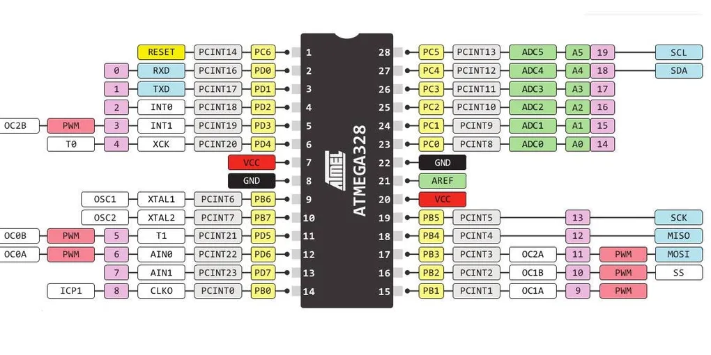
This project focuses on programming the ATmega328P directly using its hardware registers without relying on the Arduino framework.
The goal is to understand how peripherals such as GPIO and USART work internally and how software interacts with the hardware at the register level.
The first two experiments in this journey are:
- GPIO based LED control
- UART based communication
Blinky
The first experiment is a simple LED blinking program. Although blinking an LED is usually considered the “Hello World” of embedded systems, implementing it without Arduino libraries provides a better understanding of how GPIO peripherals actually work.
GPIO Registers
The ATmega328P controls its GPIO pins using three important registers:
DDRx- Data Direction RegisterPORTx- Output registerPINx- Input register
The DDRx register determines whether a pin behaves as an input or output.
For the onboard LED connected to PB5, the pin is configured as an output:
DDRB |= (1 << PB5);This sets the corresponding bit in the Data Direction Register.
To drive the pin HIGH:
PORTB |= (1 << PB5);and to toggle its state:
PORTB ^= (1 << PB5);Implementation
The program continuously toggles the LED state with a delay between each transition.
The execution flow is:
        Reset
          |
          v
+----------------------+
| Configure PB5 output |
+----------------------+
          |
          v
+----------------+
|  Set LED HIGH  |
+----------------+
          |
          v
+----------------+
|     Delay      |
+----------------+
          |
          v
+----------------+
| Toggle LED     |
+----------------+
          |
          |
          +-------> Repeat
No Arduino functions such as pinMode() or digitalWrite() are used. All interaction happens directly through the ATmega328P registers.
Learning Outcome
This simple experiment helped in understanding:
- Memory mapped hardware registers
- GPIO configuration
- Bit manipulation
- Direct peripheral control
This serves as the foundation for working with more complex peripherals such as timers, interrupts, and communication interfaces.
Echo Service
After experimenting with GPIO, the next step was establishing communication between the microcontroller and the outside world.
This project implements a simple UART echo service using the built-in USART peripheral of the ATmega328P.
USART Communication
The ATmega328P provides a USART peripheral for serial communication.
The main registers involved are:
UBRR0- Baud rate configurationUCSR0A- USART status registerUCSR0B- USART control registerUCSR0C- Frame configuration registerUDR0- Data register
Before communication begins, the USART peripheral needs to be configured with the required baud rate and communication parameters.
UART Initialization
The initialization process involves:
- Configuring the baud rate
- Enabling transmitter and receiver
- Setting the frame format
UBRR0H = (BAUD_PRESCALE >> 8);
UBRR0L = BAUD_PRESCALE;

UCSR0B |= (1 << RXEN0) | (1 << TXEN0);
This enables both receiving and transmitting functionality.
Echo Implementation
The echo service continuously checks for incoming characters.
The flow is:
          PC / Serial Terminal
                   |
                   v
          +----------------+
          |  UART Receiver |
          +----------------+
                   |
                   v
          +----------------+
          |     UDR0       |
          | Receive byte   |
          +----------------+
                   |
                   v
          +----------------+
          |  Echo Logic    |
          | Process byte   |
          +----------------+
                   |
                   v
          +----------------+
          |     UDR0       |
          | Send byte      |
          +----------------+
                   |
                   v
          PC receives echo
For example:
PC Terminal:
Hello ATmega328P

ATmega328P:
Hello ATmega328P
Polling Based Communication
The current implementation uses polling rather than interrupts.
The microcontroller continuously checks the USART status flags to determine:
- Whether new data has arrived
- Whether the transmitter is ready
While interrupt-driven communication is more efficient, polling provides a simpler way to understand the USART hardware and its registers.
Learning Outcome
Through this project, I explored:
- UART communication fundamentals
- USART register configuration
- Baud rate generation
- Hardware status flags
- Register-level peripheral programming